
I recently blogged about setting up my Raspberry Pi to use the GPIO on my OpenELEC operating system. Once I got it set up, it was time to create my first project. The basic project that is demonstrated on the official Raspberry Pi site is to light up an LED (light emitting diode). I used this basic tutorial to get it up and running and followed these coding instructions to light it up.
I didn't have any LEDs or a breadboard, so I purchased this starter kit from Sunfounder. The kit contains a lot of other great parts and tutorials to create more complex projects that I'm hoping to do in the near future.
After I had the first LED working, it was time to advance the project and apply what I had learned with one LED to many. To keep it simple, I began by adding two additional LEDs (yellow and green).
The initial LED tutorial also demonstrates how to wire up the other two LEDs required for the traffic sequence (shown in the figure below). [caption id="attachment_1051" align="aligncenter" width="300"] As I am learning about physical computing with the Pi, I'm also learning Python for the first time. Taking the basic code that was demonstrated from the official tutorial, I converted it to something that would be more reusable as my project expanded. I quickly realized that the code to turn the LEDs on and off was being repeated, so I converted it to a class called Led. The following example defines the Led class. I saved this in a file called led.py. The class contains three functions: a constructor, and on/off functions for the LED. The constructor accepts three parameters that define some characteristics about the LED being created. The pinNumber is used to setup the GPIO pin to send or stop power to the LED. The name parameter is more of a debugging tool to print out the name of the LED being turned on or off. The final parameter, duration, is used to keep the particular light on for a given length of time. The on/off functions, do not contain additional parameters, they simply set the GPIO power on or off to the given LED. As you can see, this code is just a re-organization of the same code from the Raspberry Pi tutorial. Next I had to define the traffic sequence. This example demonstrates how to setup the three LEDs in a sequence. I saved this in a file called trafficlights.py. The first 12 lines import the required libraries and setup the GPIO mode. The next 3 lines create our 3 LEDs. As defined, the red LED is setup on pin 18, yellow on pin 8, and green on pin 20. Be sure to update these to match your wiring. With the LED variables all defined, the traffic sequence can be begin. It starts by turning the red LED on. Each LED is called to turn on followed by off. Because of the duration variable defined in the Led class, in the off function, it will sleep for the given duration. The traffic sequence I have defined will begin with a red light for 5 seconds, followed by a 5 second green light, then a 2 second yellow light, and finally back to red before finishing. For this example to work, I had to create a third file called __init__.py. This file is empty, but allows my trafficlights.py file to import my Led class in a separate file. To run this example, I used putty to connect to my Raspberry Pi via the shell. Once connected I was able to run the code by using I was pretty happy with the results of this experiment that I wanted to push it further. I thought adding a "walk signal" would be a nice addition. To accomplish this, I wired two additional LEDs, a white one (the walk signal) and a yellow one that flashes when the walk time is almost over that will go solid when it is no longer safe to walk. [caption id="attachment_1052" align="aligncenter" width="169"] To perform the flashing, I added a new function to the Led class. The following example defines this function: The flash function loops over a sequence three times that turns the LED off and on every 1/2 a second. The next example updates the existing trafficlights.py code. First, the two new LEDs need to be defined. I've added this immediately after the definition of the initial LEDs. In this example, the white LED is connected to the GPIO pin 17 and the flashing LED is connected to 27. Please update accordingly for your wiring. The greenled definition also requires a slight tweak. The duration has been changed from 5 to 0. The final change is to update the traffic sequence as follows. This replaces the previously defined sequence. The start and end of the sequence remain the same in turning the red LED on and off. The green sequence is changed to also turn the white LED on at the same time. This is followed by turning the white LED off and beginning the flash sequence. When the flash sequence is done, the green LED turns off while the flash LED remains on. After the green light turns off, the yellow turns on followed by the off of the yellow and the flashing LED (as it remained on when the light turned yellow). The final result of the sequence looks pretty neat. The green light will remain on for 5 seconds. For the first 3 seconds, the white light will be on followed by 2 seconds of the LED flashing signaling the end of the walk cycle. When the green turns off and goes yellow, the previously flashing LED remains on indicating it is no longer safe to walk. I've made the final source code available on GitHub. Published on Dec 14, 2015 Tags: Python
| Raspberry Pi
| python
| raspberry pi
| gpio
Did you enjoy this article? If you did here are some more articles that I thought you will enjoy as they are very similar to the article
that you just finished reading.
Jamie Munro is the author of ASP.NET MVC 5 with Bootstrap and Knockout.js,
Knockout.js: Building Dynamic Client-Side Web Applications,
20 Recipes for Programming MVC 3,
and 20 Recipes for Programming PhoneGap. He has been developing websites and web applications for over 20 years. Jamie began his writing career in 2009. As the success of Jamie's blog grew, he turned his writing passion to books about web development in hopes that his many years of experience could be passed on to his readers. No matter the programming language you're looking to learn, I've hopefully compiled an incredible set of tutorials for you to learn; whether you are beginner
or an expert, there is something for everyone to learn. Each topic I go in-depth and provide many examples throughout. I can't wait for you to dig in
and improve your skillset with any of the tutorials below.
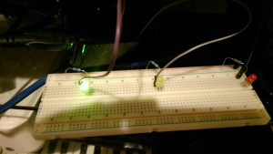 Initial wiring[/caption]
import time
import RPi.GPIO as GPIO
class Led:
	def __init__(self, pinNumber, name, duration):
		self.pinNumber = pinNumber
		self.name = name
		self.duration = duration
		GPIO.setup(pinNumber,GPIO.OUT)
	def on (self):
		print(self.name + " on")
		GPIO.output(self.pinNumber, GPIO.HIGH)
	def off (self):
		time.sleep(self.duration)
		print(self.name + " off")
		GPIO.output(self.pinNumber, GPIO.LOW)
# Next two lines only required if using OpenELEC
import sys
sys.path.append('/storage/.kodi/addons/python.RPi.GPIO/lib/')
# Import time, GPIO, and new Led class
import time
import RPi.GPIO as GPIO
from led import Led
GPIO.setmode(GPIO.BCM)
GPIO.setwarnings(False)
# Create variables to hold the 3 LEDs
redled = Led(18, "RED", 5)
yellowled = Led(8, "YELLOW", 2)
greenled = Led(20, "GREEN", 5)
#start traffic sequence
redled.on()
redled.off()
greenled.on()
greenled.off()
yellowled.on()
yellowled.off()
redled.on()
redled.off()
GPIO.cleanup()
python trafficlights.py 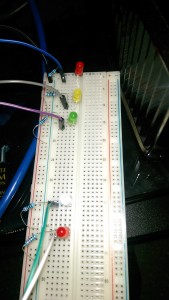 Final wiring[/caption]
	def flash (self):
		print(self.name + " flash")
		for x in range (0, 3):
			GPIO.output(self.pinNumber, GPIO.LOW)
			time.sleep(0.5)
			GPIO.output(self.pinNumber, GPIO.HIGH)
			time.sleep(0.5)
whiteled = Led(17, "WHITE", 3)
flashled = Led(27, "FLASH", 0)
greenled = Led(20, "GREEN", 0)
redled.on()
redled.off()
greenled.on()
whiteled.on()
whiteled.off()
flashled.flash()
greenled.off()
yellowled.on()
yellowled.off()
flashled.off()
redled.on()
redled.off()
Related Posts

Tutorials
Learn how to code in HTML, CSS, JavaScript, Python, Ruby, PHP, Java, C#, SQL, and more.